
Photo Orientation
|
|
Photo Orientation |
This example will show how Noobeed defines a "Photo" object, performs Interior Orientation (IO) and Relative Orientation (RO). After RO we are going to generate an epipolar geometry image, where all correspondence pixels will lie in the same row number. This type of image is very useful for surface reconstruction, Digital Elevation Model extracting. Finally we are going to combine to left and right photo, which have been already rectify to the epipolar geometry, to make an anaglyph image, a red and cyan image overlaid on top of each other. If we have an anaglyph glass, a red cyan glass, you can view the image in three dimensional visualization.
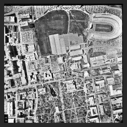
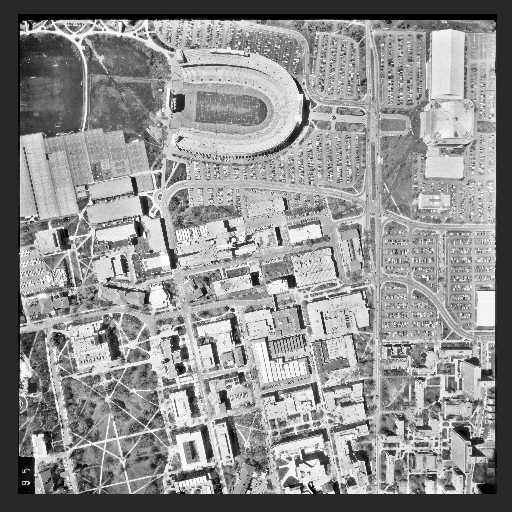
Suppose that we have 2 images, in a TIF format, as "193.tif", and "195.tif", as shown below (photos courtesy of Department of Geodetic Science, Ohio State University).
 |
 |
Defining a photo
The "193.tif" is the left photo and the "195.tif" is the right photo. First we need to define a "Photo" object, then load the image to it.
->set path "c:\WHEREEVER_YOUR_DATA_ARE"
->a = Photo()
->a.loadtif("193")
->b = Photo()
->b.loadtif("195")
Defining a camera
Now we need a camera file. It is an ASCII file which has information of an aerial camera. An example of a camera documentation file is "cam_osu.txt". It is simple to create a camera documentation file, by defining a camera object, then save it right away. For example,
->cam = Camera()
->cam.save("my_camera.txt")
What you will get is an ASCII file, name "my_camera", that you can later on edit it according to your camera information. If you do not specify a file name extension, Noobeed will give ".txt" for you.
Please notice that the camera file must have exactly either 7 or 8 lines (see details in class function SAVE of Camera) , and the first line must read "Camera". Putting a slash, "/", in front of the line, makes a comment line, and the plus sign "+" in front of a line means a continuation from the previous line.
Now we want to assign a camera to photos "a" and "b". Here is the way.
->cam = Camera()
->cam.load("cam_osu.txt")
->a.camera() = cam
->b.camera() = cam
Interoir Orientation (IO)
At this point we can do interior orientation now. However, we need observation data, which are basically observed coordinates of fiducial marks, either as matrix indices (row, column) or image rectangular coordinate (x,y). See detail in coordinate system. The observation file we are going to use is "obs_io.txt". To read it, we need a "VECIDPT2D" object, which is vector of 2D point with ID. Here is how to read observation data.
->vec1 = VecIdPt2D()
->vec1.loadsch("obs_io.txt", 193)
->vec2 = VecIdPt2D()
->vec2.loadsch("obs_io.txt", 195)
The command "loadsch", a class function of VECIDPT2D, load a portion of data that start with a specific number. For example, loadsch("obs_io.txt", 193) will starting reading data after the line containing number "193" is found. Please look at the file "obs_io.txt" again to get a more understanding. By the support of this "loadsch" function, we can put observed data of all photos in one single file.
Now it is time to compute IO of each photo.
->a.IO(vec1, "affine", 0, "193_io.txt")
->b.IO(vec2, "affine", 0, "195_io.txt")
The file "193_io.txt" and "195_io.txt" are ASCII files, which will report the quality of the IOs. Normally the standard deviation of unit weight should about 1. Please also notice the option "affine" used in one of arguments on function "IO". It requires at least 3 fiducial marks. Other options available are "conformal" and "poly2nd", which require at least 2 points and 5 points respectively.
At this point, you might want to save your photo object "a" and "b". A command, named "save", can be used for this purpose. It save a photo object in a Noobeed format, consisting of 2 files, one for data (binary) and the other for document (ASCII). See its class function for details.
Once IO is done, it is possible to convert a row and column index to a photo coordinate, and vice versa For example,
->a.rc2xpyp(500,600)
ans = ( -85.851 , 94.842)
->a.xpyp2rc(-85.851, 94.842)
ans = (500 , 600)
Now we are introducing a new class, "Model, which is to be used for a stereo model, as follows.
->M = Model(a, b)
Relative Orientation (RO)
Now we want to do relative orientation (RO). However, we need observation data, which are basically observed coordinates of same points on the left and right photo, either as matrix indices (row, column) or image rectangular coordinate (x,y). See detail in coordinate system. The observation file we are going to use is "obs_pt.txt". To read it, we need a "VECIDPT2D" object, which is vector of 2D point with ID. Here is how to read observation data.
->vec1 = VecIdPt2D()
->vec1.loadsch("obs_pt.txt", 193)
->vec2 = VecIdPt2D()
->vec2.loadsch("obs_pt.txt", 195)
Now it is time to compute RO of each photo.
->M.RO(vec1, vec2)
Since you omit the output file name in one of the function argument, Noobeed generate a result report by a default name "rpt_ro.txt".
Image normalization
From here we are not going to do an absolute orientation (AO), rather we are going to do something that is exclusive to digital photogrammetry, to generate a pair of epipolar geometry images. This can be done by:
->M_new = M.normalize("bilinear")
That is it. Now M_new is another model, having its own left photo and right photo. This model is very useful for doing image matching, a way to generate a DEM and surface reconstruction, since searching a corresponding point can be confined in one dimension. Image matching is still one of the major not-yet-to-solve problems in digital photogram.
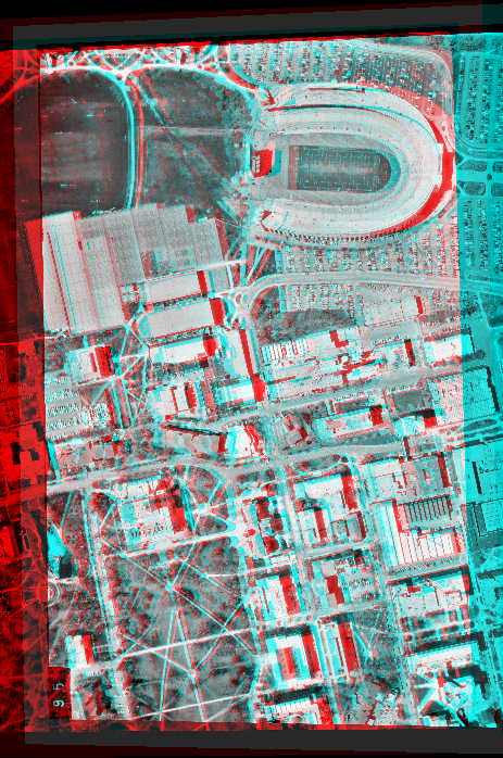
Since M_new is a so-called y-parallax free model, we are going to produce a y-parallax free anaglyph image for a 3D visualization. The statement is
->Img = M.anaglyph(90)
The result is an Image_rgb object, which later on can be save as an RGB TIF file. The first argument value, 90, is the amount of shift, in photo coordinate system unit (millimeter), that the right photo will be move from the left photo. Put it in this way, suppose that we put the right photo exactly on top of the left photo, the amount of shift is zero. Then we start moving the right photo for a distance of 90 millimeters to the right, indicated by the positive sign. The overlap area where the two photos are, is extracted to produce an anaglyph image. This is done by assigning a gray scale of the left image as a shade level of red color and assigning a gray scale of the right image as a shade level of green and blue color, a cyan shade color. Here is the anaglyph image.
It is worthwhile to mention here that, the 3D anaglyph image, if made from known exterior orientation photos, is able to be a 3D backdrop of a map. This might be called a 3D ortho-photo. The product would be a sort of new excitement to map users. However, one drawback is it is not possible to maintain the map grid lines being horizontal and vertical, because we need to orient the 3D anaglyph such that its base line is in the horizontal direction.